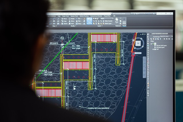
Exploded view drawings in sheet metal and fabrication detailing break down assemblies into individual components, guiding fabricators through accurate cutting, forming, and assembly. Standardized symbols enhance communication, streamline processes, reduce errors, and improve efficiency, ultimately optimizing sheet metal and fabrication detailing quality and timelines.
Exploded view and assembly drawings are invaluable tools for sheet metal fabricators, simplifying complex projects. This article guides you through these powerful methods, enhancing your understanding of exploded views for sheet metal components and optimizing the fabrication process. Learn effective assembly techniques, essential detailing tips for precise cuts and fits, and standardized symbols to streamline communication across teams. Streamline your sheet metal fabrication with these practical insights tailored for precision and efficiency.
Understanding Exploded View Drawings for Sheet Metal
Exploded view drawings are a powerful tool in the realm of sheet metal fabrication detailing, offering a clear and detailed representation of an assembled product’s components. These drawings provide a step-by-step breakdown of how various parts interlock and connect, making them invaluable for fabricators. By presenting each element separately while maintaining their relative positions, exploded views offer a unique perspective that simplifies the complex assembly process.
For sheet metal workers, these drawings serve as a comprehensive guide, ensuring every fold, bend, and fastening point is accurately represented. This level of detail allows fabricators to easily navigate the fabrication process, from cutting and forming the sheet metal to assembling it into a functional whole. With exploded views, there’s no mistaking the correct placement or sequence of operations, leading to more efficient production times and higher-quality outcomes.
Assembly Techniques to Streamline Fabrication Process
In the realm of sheet metal and fabrication detailing, efficient assembly techniques are key to streamlining the entire fabrication process. By employing strategic methods, manufacturers can enhance productivity while ensuring precision and quality in final products. One effective strategy involves utilizing exploded view drawings that deconstruct a complex assembly into individual components, offering a clear visual guide for fabricators.
These detailed illustrations provide a step-by-step breakdown of how each part interlocks, allowing workers to understand the relationship between components without having to refer back to intricate 3D models or prototypes. Additionally, assembly drawings with precise measurements and annotations facilitate accurate placement and fitting during fabrication, minimizing errors and rework. Such techniques prove invaluable in accelerating production timelines and enhancing overall efficiency.
Detailing Tips for Accurate Cut and Fit
When it comes to sheet metal and fabrication detailing, achieving precise cut and fit is paramount for successful assembly. Pay meticulous attention to dimensions, tolerances, and notch placements in your exploded view drawings. Each line, mark, and measurement should be accurate to ensure the various parts interlock seamlessly during construction.
Consider incorporating detailed cross-sections or callouts where necessary to clarify complex joints. Use standard notation and industry symbols to convey critical information clearly. This level of meticulousness in your fabrication detailing will streamline the cutting, forming, and assembly processes, ultimately leading to higher-quality end products.
Standardized Symbols for Efficient Communication
Standardized symbols play a pivotal role in enhancing communication between designers, engineers, and fabricators when it comes to sheet metal and fabrication detailing. These universally accepted icons and notations simplify complex assembly processes, ensuring everyone involved understands the desired outcome. For instance, specific symbols indicate bend angles, punch locations, and tab placements, streamlining the interpretation of exploded view drawings.
By utilizing these standardized symbols, teams can reduce errors and misinterpretations, making the fabrication process more efficient. This standardization facilitates quick reference for fabricators, enabling them to translate design intent into physical parts with precision. As a result, projects can be completed faster, and costs can be optimized through this streamlined communication method in sheet metal fabrication detailing.
Exploded view and assembly drawings are indispensable tools in the world of sheet metal fabrication, offering a clear and detailed roadmap for creating complex components. By understanding these diagrams, mastering assembly techniques, and adhering to standardized symbols, fabricators can streamline their processes, ensure precise cuts and fits, and enhance communication across teams. These practices ultimately lead to more efficient and high-quality sheet metal fabrication detailing, making them essential skills for any professional in this domain.
